Arida Base 160 WiFi Single Room Ventilator

Safety requirements
Read the user manual carefully before installing and using the ventilation unit. Installation and operation must be carried out in accordance with this manual and applicable national building, electrical and technical regulations.
- The warnings in this manual must be taken seriously as they contain important safety information.
- Failure to follow the safety instructions may result in personal injury or damage to the product.
- Read the manual carefully and keep it for as long as you use the ventilation unit.
- This appliance can be used by children aged from 8 years and above if they have been given supervision or instruction concerning use of the appliance in a safe way. Do not allow children to play with the appliance or make any maintenance on it without supervision.
- If the power cord is damaged, it must be replaced by the manufacturer or a certified electrician in order to avoid a risk of fire or electric shock. Do not operate the product with a damaged cord.
- Never pull on the cord – this may cause a short circuit, damage to the cord, fire or electric shock.
- It is recommended to install the ventilation unit more than 2.1 m above the floor so that children cannot reach the installation.
- Take precautions to prevent backflow of combustion gases from open gas appliances. Such gases can cause carbon monoxide poisoning.
- Insert batteries with correct polarity. Do not charge non-rechargeable batteries. Keep the remote control away from children - batteries can be swallowed and cause accidents.
- Do not use with a clogged filter – this may damage internal components and is not covered by the product warranty.
- Always disconnect power before installation or maintenance.
- Keep the product's power cord away from heat sources.
- The room fan and used batteries are delivered to a suitable waste collection point (WEEE).
Application and contents of the box
Arida Base 160 WiFi is designed for air exchange in apartments, villas, hotels, cafes and other residential and public buildings. The unit is equipped with a ceramic energy regenerator and a fan that supplies fresh air and extracts used air with energy recovery.
- Designed for through-the-wall installation – fits walls from 280 mm to 470 mm thick.
- Designed for continuous operation with power connected.
- The air transported must not contain explosive mixtures, chemical vapors, coarse dust, soot, oil droplets, sticky substances, pathogens or other harmful substances.
Contents of the box
- Ventilation unit – 1 pc.
- Accessory bag (wall plug and screws) – 1 pc.
- Remote control – 1 pc.
- Quick start guide – 1 pc.
Technical specifications
| Property | Value |
|---|---|
| Voltage | 100-240V |
| Frequency | 50/60Hz |
| Power consumption (L/M/H) | 4.7 / 5.6 / 6.5W |
| Airflow (L/M/H) | 30 / 50 / 60 m³/h |
| Noise level (L/M/H) | 18.9 / 25.2 / 28.7 dB(A) |
| Heat recovery | Up to 97% |
| Air duct diameter | 158mm |
| Energy labeling | Class A+ |
| Mounting type | Wall mounting (through) |
| Wall thickness compatibility | 280–470mm |
| Operating temperature (outdoor) | -20°C to +50°C |
| Max. relative humidity | Below 80% |
| Net weight | 3.9 kg |
Design and function
The unit consists of a telescopic air duct with adjustable length, a ventilation unit and a ventilation hood. A pre-filter and ceramic energy regenerator are located inside the inner duct. The ceramic energy regenerator extracts energy from the extract air to heat or cool the supply air.
Operating modes
- Supply air mode: The fan runs continuously and supplies fresh air from outside.
- Extraction mode: The fan runs continuously and extracts used indoor air.
- Regeneration mode (heat recovery): The unit automatically switches between supply air and extract air every 75 seconds. Warm indoor air heats the ceramic regenerator, which then transfers the heat to cold fresh air from outside. Heat recovery up to 97%.
Installation guide
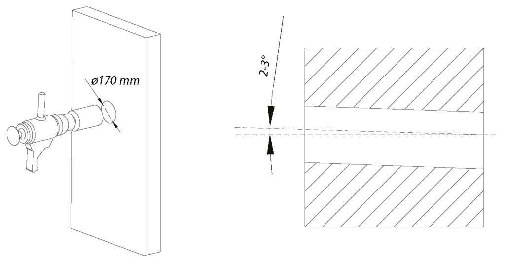
Step 1 – Drill the hole in the wall
Drill a Ø165–170 mm round hole horizontally with a 2–3° slope outwards through the entire wall. For best performance, we recommend that the indoor unit is mounted with a minimum distance of 10 cm from the outer edge of the indoor unit to the ceiling.
Tip! Use a core drill, or a drill with a hole saw and extension.
Step 2 – Attach the pipe to the wall
If you have a wooden wall with a vapor barrier, you should thread the included rubber sleeve over the PVC pipe to ensure a satisfactory seal. Push the pipe into the wall and adjust so that it is perfectly straight. Use construction foam, acrylic or glue to attach the pipe evenly so that it is flush with the interior wall. Allow the fastening material to dry.

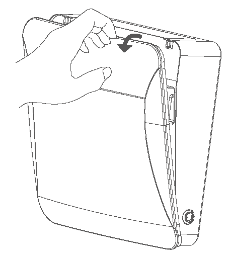
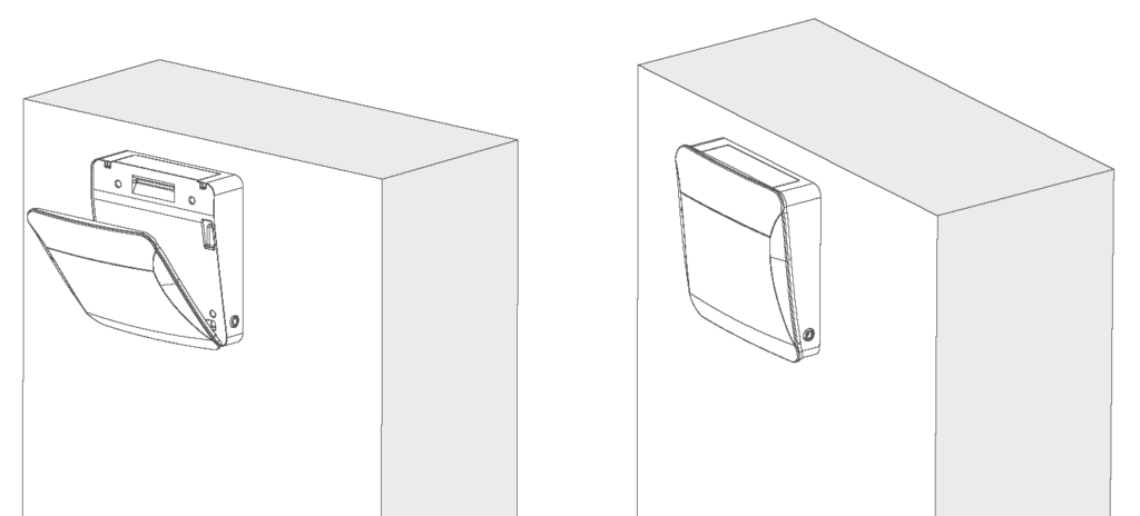
Step 3 – Dismantle the indoor unit
Pull off the panel on the indoor unit and unscrew the mounting plate from the main unit.

Step 4 – Customize the indoor unit
Thread the core loosely into the mounting plate for the indoor unit, then insert the core with the indoor unit into the pipe as one piece. Wait to connect the core to the mounting plate.
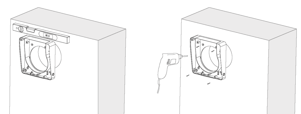
Step 5 – Screw the mounting plate in place
Use a spirit level when attaching the mounting plate to the wall with the included wall plugs and screws.
Important! Pull the core out slightly and make sure that the core is not in tension against the mounting plate. The core must be removed for maintenance and must be loose.
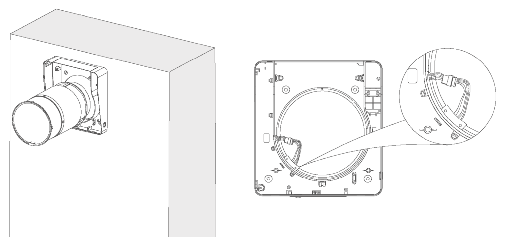
Step 6 – Insert the core and connect the indoor unit
Connect the connector together. Carefully lay the cable along the inside of the indoor unit, over the air passage, as shown in the illustration. The connection plugs should face left, downwards.

Step 7 – Install the indoor unit
Fix the main body to the mounting plate with the supplied screws and replace the panel. The installation is complete.
To achieve the best possible effect, the heat exchanger and air filter must be cleaned regularly. See the maintenance section.
Functional description and LED indicators

The control panel is located on the bottom of the unit and contains three LED indicators (LED1, LED2, LED3), an infrared receiver, a humidity sensor and a RESET button.
LED indicators
| Light signal | Importance |
|---|---|
| Green light | Supply air mode is active |
| Red light | Extraction mode is active |
| Blue light | Regeneration mode (heat recovery) is active |
| Flashing blue light | Humidity-triggered exhaust mode |
| Flashing red light | Filter cleaning reminder (after 960 hours of operation) |
| LED1 red fast flash ×4 | Filter timer is reset |
RESET button
The RESET button is operated with a SIM card pin or other pin-shaped object with a diameter of less than 2 mm. Avoid sharp objects.
| Pressure | Function |
|---|---|
| Short press | Select speed 1 → speed 2 → speed 3 → off (circulating) |
| Hold for 3 seconds. | WiFi connection mode (LED1 green flashing) |
| Hold for 6 seconds. | Set as leader device in pairing mode (LED1 blue blink) |
| Hold for 9 seconds. | Set as follower device in pairing mode (LED1 + LED2 blue flash) |
| Hold for 12 seconds. | Reset filter alarm |
| Hold for 15 seconds. | Reset to factory settings |
Remote control
Insert AAA batteries and close the battery cover until it clicks into place. Point the remote control at the control panel on the bottom of the unit. Max. range: 15 meters (line of sight).
| Button | Function |
|---|---|
| Speed + / – | Adjust between 3 fan speeds |
| Mode switching (M) | Choose between extract air mode, supply air mode and ventilation mode |
| Light on/off | Turn LED indicators on or off |
| Boost mode | Runs at top speed for 30 minutes |
| Filter (hold 5 sec.) | Reset filter alarm after cleaning |
| Power on/off | Turn the device on or off |
Pairing of leader and follower devices
Multiple units can be connected in a master/slave system where one master unit controls one or more slave units via remote control.
Setting up the management unit
- Hold the RESET button for 6 seconds . LED1 flashes blue – the device is in pairing mode as a leader.
Setting up a follower device
- Hold the RESET button for 9 seconds . LED1 and LED2 flash blue – the device is in pairing mode as follows.
- Pairing must be completed within 1 minute. The devices should be close to each other during the process.
- Successful pairing: The leader unit's LED1 flashes quickly three times and then turns off.
- Pairing failed: LED light flashes for 1 minute and turns off automatically.
In regeneration mode, the follower unit runs in the opposite direction to the leader. In other modes, both run in the same direction.
WiFi setup and app
Download the Smart Life app from the App Store or Google Play.
Pre-setup requirements: The router must use 2.4 GHz network (not 5 GHz). Bluetooth must be enabled on the mobile phone.
- Download Smart Life from the App Store or Google Play.
- Connect your mobile phone to WiFi (2.4GHz) and turn on Bluetooth. Make sure the device and phone are on the same network.
- With the device in standby mode: Press and hold the RESET button for 3 seconds (use SIM card pin) until LED1 flashes green. The device is now in WiFi setup mode.
- Open the Smart Life app, log in and tap the + sign in the top right. Select "Add Device".
- The app automatically finds the device when Bluetooth is on and the device is in the correct mode.
- Select your home network's WiFi name and enter the password.
- After successful connection, you can find the device in the overview in the Smart Life app.
Humidity control via the app
Set the humidity limit between 50-95%. In regeneration mode, the exhaust mode is automatically activated when the humidity exceeds the limit, and the unit returns to the previous mode when the humidity drops 10 percentage points below the set limit.
Reset WiFi
Open the Smart Life app, press and hold the device you want to disconnect and select "Remove device". Confirm to disconnect WiFi.
Maintenance and cleaning
Always disconnect power before maintenance.
How to disassemble for cleaning
- Remove the front panel from the indoor unit.
- Disconnect the wires between the indoor unit and the inner duct, and loosen the inner duct.
- Remove the ceramic regenerator and primary filter from the inner air duct.
- Clean according to the table below and put everything back in reverse order.
| Component | Frequency | Method |
|---|---|---|
| Pre-filter | 4 × per year | Wash or vacuum. Allow to dry completely before installation. Lifetime approx. 3 years. |
| Ceramic energy regenerator | 4 × per year | Rinse directly with water. Leave in the sun until completely dry. Vacuum at least once a year. |
| Fan (impeller) | 1 × per year | Remove the inner bracket and take out the fan. Use a soft brush, cloth or vacuum cleaner. Do not use water or abrasives. |
| F7 filter (optional) | 4 × per year | Cannot be washed - vacuum only, or replace if necessary. |
Storage and transportation
- Store the device in its original packaging in a dry place.
- The storage location must be free from aggressive vapors and chemical mixtures that could cause corrosion or deformation.
- Avoid mechanical shocks during handling and transport.
Troubleshooting
| Error | Possible cause | Solution |
|---|---|---|
| The fan does not start. | No power supply | Check that the device is properly connected to power. |
| The fan does not start. | Motor is stuck or fan blades are clogged | Turn off the device, clean the fan blades and restart. |
| Low airflow | Low speed setting | Increase fan speed |
| Low airflow | Dirty filters, fan or exchanger | Clean or replace filter and clean fan and exchanger |
| Noise/vibrations | Dirty fan blades | Clean the fan blades |
| Noise/vibrations | Loose screws on the chassis or ventilation hood | Tighten all screws |
| Pairing failed | Leader/follower was set up with different remote controls | Use the same remote control for both devices |
| Pairing failed | Lots of metal or interference sources nearby | Remove the sources of interference or move the installation location. |
| Pairing failed | Too long distance between devices | Move the devices closer together (max. 15 m clear line of sight) |
| WiFi connection failed | The phone is connected to 5 GHz network | Switch to 2.4 GHz network |
| WiFi connection failed | Incorrect connection to public WiFi | Use a private home network with your own password |
| WiFi connection failed | Bluetooth on your phone is disabled. | Turn on Bluetooth and try again. |