Arida Venti 110 WiFi Single Room Ventilator

Safety requirements
Read the user manual carefully before installing and using the ventilation unit. Installation and operation must be carried out in accordance with this manual and applicable national building, electrical and technical regulations.
- The warnings in this manual must be taken seriously as they contain important safety information. Failure to comply could result in personal injury or damage to the product.
- Read the manual carefully and keep it for as long as you use the ventilation unit.
- This appliance can be used by children aged from 8 years and above if they have been given supervision or instruction concerning use of the appliance in a safe way. Do not allow children to play with the appliance or make any maintenance on it without supervision.
- If the power cord is damaged, it must be replaced by the manufacturer or a certified electrician. Never use the product with a damaged cable or extension cord.
- Never pull on the cord – this may cause a short circuit, damage to the cable, fire or electric shock.
- It is recommended to mount the ventilation unit higher than 2.1 m above the floor so that children cannot reach the installation.
- Take precautions to prevent backflow of combustion gases from open gas appliances into adjacent rooms. Such gases can cause carbon monoxide poisoning.
- Insert batteries with correct polarity. Do not charge non-rechargeable batteries. Keep the remote control away from children - batteries can be swallowed and cause accidents.
- Do not operate the unit with a clogged filter - this may damage internal components and reduce the life span. Not covered by the product warranty.
- Always disconnect power before installation or maintenance.
- Keep the product's power cord away from heat sources.
- The product is not suitable for installation in exterior windows or walls.
- The room fan and used batteries are delivered to a suitable waste collection point (WEEE).
Application and contents of the box
Arida Venti 110 WiFi is designed for air exchange in apartments, villas, hotels, cafes and other residential and public buildings. The device is equipped with a ceramic energy regenerator and a fan that supplies fresh air and extracts used air with heat recovery. The model has a built-in CO₂ sensor and supports the connection of a negative ionizer (purchased separately).
- Designed for through-the-wall installation – fits walls from 270 mm to 500 mm thick.
- The indoor unit is attached with magnets and requires no screws for assembly.
- Ingress Protection rating: IPX4 (protected against splashing water).
- Designed for continuous operation with power connected.
- The air transported must not contain explosive mixtures, chemical vapors, coarse dust, soot, oil droplets, sticky substances, pathogens or other harmful substances.
Technical specifications
| Property | Value |
|---|---|
| Voltage | 220-240 V (compatible with 100-240 V) |
| Frequency | 50/60Hz |
| Power consumption (L/M/H) | 6 / 7 / 7.8W |
| Air flow supply/extract (L/M/H) | 10 / 20 / 25 m³/h |
| Airflow regeneration (L/M/H) | 5 / 10 / 12.5 m³/h |
| Max. airflow (Boost mode) | 30 m³/h |
| Noise level | 31.2 dB(A) |
| Heat recovery | Up to 97% |
| RPM (L/M/H) | 1100 / 2200 / 2600 rpm |
| Max. speed | 2950 rpm |
| Air duct diameter | 110mm |
| Energy labeling | Class A |
| Ingress Protection | IPX4 |
| Mounting type | Wall mounting (through) |
| Wall thickness compatibility | 270–500mm |
| Operating temperature (outdoor) | -20°C to +50°C |
| Max. relative humidity | Below 80% |
| Net weight | 3.4 kg |
Design and function
The unit consists of a telescopic air duct with adjustable length, a ventilation unit and an external ventilation hood. The pre-filter and ceramic energy regenerator are located inside the inner duct. The regenerator is equipped with a pull cord that makes it easy to remove for cleaning.
The indoor unit is attached magnetically to the mounting plate – no screw fastening of the unit itself is required. This makes it easy to remove the indoor unit for maintenance and cleaning.
Operating modes
- Supply air mode: The fan runs continuously and brings in fresh air from inside. When pairing two units, one runs in supply air and the other in exhaust air.
- Extraction mode: The fan runs continuously and extracts used indoor air.
- Regeneration mode (heat recovery): The unit automatically switches between supply air and extract air every 75 seconds. Warm indoor air heats the ceramic regenerator, which then transfers the heat to cold fresh air from outside. Heat recovery up to 97%.
Installation guide
Installation and connection should only be carried out by qualified personnel.
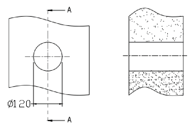
Step 1 – Drill the hole in the wall
Drill a Ø120 mm round hole horizontally through the entire wall with a 2–3° outward slope . For best performance, we recommend at least 15 cm clearance from the outer edge of the indoor unit to the wall or ceiling.
Tip! Use a core drill, or a drill with a hole saw and extension.
Step 2 – Attach the pipe to the wall
Push the PVC pipe into the hole and adjust the length to the thickness of the wall. Use construction foam, acrylic or glue to attach the pipe evenly so that it is flush with the interior wall. If you have a wooden or plaster wall, you should seal it extra well around the pipe. Let the fixing material dry completely before continuing.

Step 3 – Install the outer valve cover
Remove the valve cover and dismantle it. Place the base on the outside against the wall so that the arrow on the base points downwards. Mark the 4 fixing points, drill holes and secure the base with plugs and screws. Click the cover into place by aligning the locking hooks with the grooves in the base – the arrow on the cover should point downwards.
Step 4 – Install the mounting plate
Use a spirit level to ensure that the mounting plate is hanging straight. Note that the small plastic block on the metal plate should sit over the round hole. Align the mounting plate with the hole and secure it with screws and wall plugs.

Step 5 – Customize and install the kernel
Thread the core loosely into the mounting plate, and insert the core and mounting plate into the pipe as one unit. The connection plugs should face downwards . Wait to connect the core to the mounting plate until everything is seated correctly.
Important! Pull the core out slightly and make sure it is not tight against the mounting plate. The core must be removed for maintenance and must be loose.

Step 6 – Connect the indoor unit to the core
Hold the indoor unit in place while connecting the connectors.
Tip! Rotate the indoor unit clockwise a few times so that the wires twist slightly. This will help them stay in place.

Step 7 – Place the wires in the groove
Make sure that all wires are properly inserted into the groove on the indoor unit and that they do not protrude to the outside. Protruding wires may create a gap between the indoor unit and the mounting plate.
Step 8 – Attach the indoor unit to the mounting plate
Press the bottom of the indoor unit against the wall so that the wires do not fall out of the groove. Then press the top of the indoor unit against the magnets on the mounting plate. The indoor unit has two holes that pass over the magnets at the top of the plate - these hold the indoor unit securely in place. No screws are required.
After installation: Check that there is no visible gap between the indoor unit and the mounting plate. If there is, the wires are probably not installed correctly – take down the indoor unit, place the wires correctly in the groove and reinstall.
To achieve the best possible performance, the heat exchanger and air filter must be cleaned regularly. See the maintenance section.

Operation – buttons and remote control
Buttons on the device
| Button | Function |
|---|---|
| Top button – MODE | Switches between extract air mode, supply air mode and ventilation mode (regeneration) |
| Middle button – FAN SPEED | Switches between 3 fan speeds |
| Lower button – ON/OFF | Turns the device on or off |
Remote control
Insert button cell (CR2025) before use. Turn the battery cover clockwise until the triangle arrow points to the locked symbol. To remove the battery: Turn counterclockwise until the arrow points to the unlocked symbol. Point the remote control directly towards the front of the unit when in use.
| Button | Function |
|---|---|
| Speed + / – | Adjust between 3 fan speeds |
| Mode switching | Choose between extract air mode, supply air mode and ventilation mode |
| Light on/off | Turn LED indicators on or off |
| Boost mode | Runs at highest speed for 30 minutes, then automatically stops |
| Ionization on/off | Turns negative ionizer on/off (ionizer purchased separately) |
| Filter (hold 5 sec.) | Reset filter alarm after cleaning (default interval: 1600 hours) |
| Power on/off | Turn the device on or off |
Status light – meaning
| Light signal | Importance |
|---|---|
| Green light – supply air | Supply air mode is active |
| Red light – exhaust | Extraction mode is active |
| Blue light – regeneration | Regeneration mode (heat recovery) is active |
| Blue light ON (off state) | Leader/follower pairing is active |
| Green light ON | WiFi connected and IoT function enabled |
| Red light ON | Filter cleaning reminder |
| Purple light ON | Leader device in leader/follower mode with active IoT connection |
| Green light slowly flashing | Automatic ventilation function is active |
| Blue light slowly flashing | Free cooling function is active |
| Red light flashes 3 times | Filter cleaning has been registered and counter reset |
Pairing of leader and follower devices
Multiple units can be connected in a leader/follower system. The leader unit is controlled via remote control or app, while the follower unit automatically synchronizes with the leader. The leader can only be connected to one follower.
Setting up the management unit
- Connect power to the device. In off state: Press and hold the MODE button for 5 seconds until the status light flashes blue slowly. The device is now set to the leader role.
Setting up a follower device
- Connect power to the device. In off state: Press and hold the MODE button for 5 seconds until the status light flashes green slowly. The device is now set to follower role.
- Both devices must be put into pairing mode within 1 minute and should be close to each other during the process.
- Successful pairing: The status light on both devices turns blue and stays on.
- Pairing failed: The status lights flash for 1 minute and then turn off automatically.
Reset pairing
In off state: Press and hold the FAN SPEED button for 5 seconds on the paired device until the status light flashes blue slowly. Repeat on the other device within 1 minute. Both devices will be reset to default with no role assigned.
How the system works
- Without role assignment, one remote control can control one or more devices simultaneously.
- After role assignment, only the leader unit responds to the remote control. The follower unit synchronizes with the leader.
- In regeneration mode, the follower unit runs in the opposite direction to the leader, for optimal air circulation. In other modes, both run in the same direction.
- Max. range between leader and follower: 15 meters (unobstructed line of sight). The signal can penetrate 180 mm thick brick walls.
WiFi setup and app
Download the Smart Life app from the App Store or Google Play. The app also supports control via Google Home and Amazon Alexa.
Pre-setup requirements: The router must use 2.4 GHz network (not 5 GHz). Bluetooth must be enabled on the mobile phone, and the device and the phone must be within the same WiFi coverage.
- Download Smart Life from the App Store or Google Play.
- Connect your mobile phone to WiFi (2.4 GHz) and turn on Bluetooth.
- With the device in off state: Press and hold the ON/OFF button for 5 seconds until the status light flashes red slowly. The device is now in WiFi setup mode.
- Open the Smart Life app, log in and tap the + sign in the top right. Select "Add Device".
- The app automatically finds the device when Bluetooth is enabled and the device is in the correct mode.
- Select your home network's WiFi name in the app – it must match the network your phone is connected to – and enter the WiFi password.
- After successful connection, you can find the device in the overview on the home screen of the Smart Life app.
App features
- On/off control and mode selection
- Fan speed and Boost mode
- LED light on/off
- Ionization on/off (when ionizer is connected)
- 12-hour timer control
- CO₂ control: When a CO₂ sensor is connected, you can set a limit value from 400 to 2000 ppm. If the indoor CO₂ concentration exceeds the limit in regeneration mode, the supply air mode is automatically activated to supply fresh air. The unit returns to the previous mode when the CO₂ level falls below the set limit.
- Humidity control (optional): Set humidity limit between 40-95%. In regeneration mode, the exhaust mode is automatically activated when the humidity exceeds the limit, and the unit returns to the previous mode when the humidity drops 5 percentage points below the set limit.
- Free cooling: When the outdoor temperature is comfortable, the unit can operate in pure supply air mode without heat recovery. Adjustable temperature limit: 10–29 °C.
- Real-time display of CO₂ level and outdoor temperature (when the unit is in supply air or regeneration mode)
- Filter alarm and editable device name
Reset WiFi
Open the Smart Life app, press and hold the device you want to disconnect and select "Remove device" at the bottom of the screen. Confirm to disconnect WiFi.
Maintenance and cleaning
Always disconnect the power before maintenance. Disconnect the connection wires between the indoor unit and the inner duct, and take down the indoor unit and the inner duct from the wall separately.
Note: The ceramic energy regenerator is fragile – pull it out carefully to avoid damage.
| Component | Frequency | Method |
|---|---|---|
| Pre-filter | 4 × per year | Wash or vacuum. Allow to dry completely before installation. Lifetime approx. 3 years. |
| Ceramic energy regenerator | 4 × per year | Rinse gently directly with water. Leave in the sun until completely dry. Vacuum at least once a year. |
| Fan (impeller) | 1 × per year | Remove the inner bracket and take out the fan. Use a soft brush, cloth or vacuum cleaner. Do not use water or abrasives. |
| F7 filter (optional) | 4 × per year | Cannot be washed - vacuum only, or replace as needed. Contact seller for replacement filter. |
Storage and transportation
- Store the device in its original packaging in a dry place.
- The storage location must be free from aggressive vapors and chemical mixtures that could cause corrosion or deformation.
- Avoid mechanical shocks during handling and transport.
Troubleshooting
| Error | Possible cause | Solution |
|---|---|---|
| The fan does not start. | No power supply | Check that the device is properly connected to power. |
| The fan does not start. | Motor is stuck or fan blades are clogged | Turn off the device, clean the fan blades and restart. |
| Low airflow | Low speed setting | Increase fan speed |
| Low airflow | Dirty filters, fan or exchanger | Clean or replace filter, and clean fan and exchanger |
| Noise/vibrations | Dirty fan blades | Clean the fan blades |
| Noise/vibrations | Loose screws on the chassis or ventilation hood | Tighten all screws |
| Gap between indoor unit and mounting plate | Wires sticking out of the track | Take down the indoor unit, place the wires correctly in the groove and reassemble. |
| Pairing failed | Leader/follower was set up with different remote controls | Use the same remote control for both devices |
| Pairing failed | Lots of metal or interference sources nearby | Remove the sources of interference or move the installation location. |
| Pairing failed | Too long distance between devices | Move the devices closer together (max. 15 m clear line of sight) |
| WiFi connection failed | The phone is connected to 5 GHz network | Switch to 2.4 GHz network |
| WiFi connection failed | Incorrect connection to public WiFi (hotel, shopping mall, etc.) | Use a private home network with your own password |
| WiFi connection failed | Bluetooth on your phone is disabled. | Turn on Bluetooth and try again. |